Calculators
Flow Velocity
Analyze fluid velocities and flow regimes in wellbore
The Flow Velocity calculator analyzes fluid velocities in the tubing-casing annulus and determines the flow regime based on gas and liquid rates.
| Field | Description |
|---|
| Casing ID (in) | Casing inner diameter |
| Component OD (in) | Tubing or rod OD in annulus |
| Field | Description |
|---|
| Liquid Rate (bbl/day) | Total liquid production rate |
| Gas Rate (Mscf/day) | Gas production rate |
| Pump Intake Pressure (PSI) | Pressure at pump intake |
| Field | Description |
|---|
| Gas Specific Gravity | Gas gravity relative to air |
| Field | Description |
|---|
| Bottom Hole Temp. (°F) | Reservoir temperature |
| Field | Description |
|---|
| Mole Frac. N₂ | Nitrogen mole fraction |
| Mole Frac. CO₂ | Carbon dioxide mole fraction |
| Mole Frac. H₂S | Hydrogen sulfide mole fraction |
| Output | Description |
|---|
| Combined Velocity (ft/sec) | Superficial velocity of combined fluids |
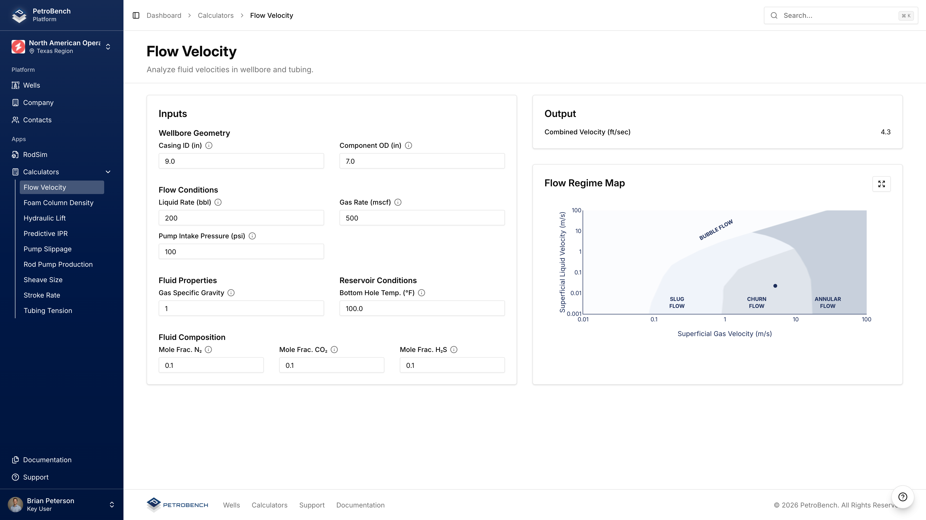
Visual chart showing flow regime based on superficial gas and liquid velocities:
- Slug Flow - Intermittent gas slugs
- Churn Flow - Chaotic, oscillating flow
- Annular Flow - Gas core with liquid film
- Bubble Flow - Dispersed gas bubbles in liquid
The current operating point is plotted on the map.
- Identify problematic flow regimes (slug flow)
- Evaluate gas interference potential
- Size tubing for optimal flow
- Assess artificial lift requirements